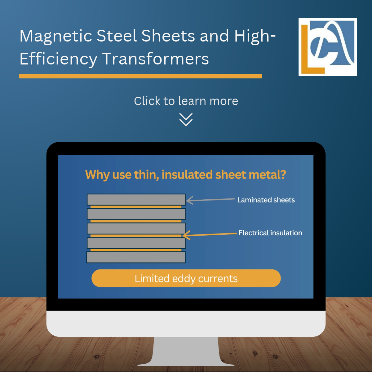
In an industrial transformer operating at 50 or 60 Hz, the magnetic circuit generally consists of a stack of magnetic laminations. These thin, individually insulated laminations limit eddy currents. Their quality and assembly have a direct impact on the transformer’s efficiency, particularly on iron losses.
Overall efficiency also depends on the windings, the load factor, the temperature, and the operating conditions.
The Role of the Magnetic Circuit
In an electrical transformer, the alternating current flowing through the primary winding creates a varying magnetic flux. The core channels this flux to the secondary winding, across which a voltage is induced.
In a solid steel core, this varying magnetic flux would induce significant eddy currents, which cause energy losses and heating. To limit this phenomenon, the magnetic circuit is divided into thin laminations coated with an insulating layer, which are then stacked to form the laminated core.
The Causes of Iron Losses
As soon as power is applied to the transformer, the magnetic circuit dissipates a portion of the energy it receives. These losses, known as iron losses, occur even when the transformer is operating at no load. They are primarily caused by hysteresis and eddy currents.
Hysteresis losses
The magnetic flux varies periodically under the influence of the alternating current. The core material then undergoes successive cycles of magnetization and demagnetization, which result in energy dissipation in the form of heat. These losses depend, in particular, on the material’s properties, the frequency, and the level of magnetic induction. The choice of magnetic steel must therefore be tailored to the transformer’s operating conditions.
Eddy-current losses
The varying magnetic flux induces eddy currents in the core. The magnitude of the associated losses depends, in particular, on the frequency of the magnetic flux, the magnetic induction, and the thickness of the laminations. To minimize these losses, the core is made up of thin laminations that are electrically insulated from one another, which reduces the flow of these currents and the resulting heat generation.
The Relationship Between Magnetic Sheets and Efficiency
A suitable magnetic core can reduce some of the no-load losses. This reduction is particularly significant when a transformer remains energized for long periods, even when the connected load is operating at low capacity.
Iron losses must be distinguished from Joule losses in the windings. The latter increase with the square of the current supplied to the load. A high-efficiency transformer therefore relies on a coherent system comprising the magnetic circuit, windings, sizing, cooling, and load factor.
The quality of magnetic sheets and their assembly
The characteristics of magnetic sheets that affect performance
Several characteristics influence the performance of magnetic sheets, including their specific losses—given for a reference frequency and induction—their thickness, their silicon content, and their magnetic permeability. Silicon increases the electrical resistivity of the steel, which helps limit eddy currents.
Grain-oriented steel sheets are particularly well-suited when the magnetic flux follows a preferred direction. The choice of material must also take into account the operating frequency of the transformer.
The cutting and assembly of the core also play an important role. A damaged insulating coating, poorly fitted joints, or improper clamping can increase losses and vibrations. The core’s performance therefore depends on the properties of the steel sheets and on the precision of their manufacture and assembly.
Effects on Temperature and Noise
Reducing iron losses limits core heating. The transformer’s temperature also depends on losses in the windings, ventilation, ambient temperature, and load factor. For more information on this topic, see our article on “Heating and Insulation Classes of Transformers.”
Metal sheets also deform very slightly under the effect of alternating current. This phenomenon, called magnetostriction, contributes to the transformer’s normal humming sound. The tightness of the core, the fasteners, and the power supply conditions can also affect this noise. See our article on transformer noise.
Selecting a High-Efficiency Transformer
To compare two transformers, you must examine their no-load and load losses and then relate them to the actual operating conditions of the system. A stated efficiency rating without an indication of the load factor is not sufficient to estimate energy losses over time.
Choosing the right power rating is also essential. An incorrectly sized transformer may operate far from its intended load rating or overheat. Our guide explains how to calculate the required power of a transformer.
Finally, the frequency, operating mode, ambient temperature, and presence of harmonics must be reported to the manufacturer. This information allows the magnetic circuit and windings to be sized according to actual operating conditions.
A design tailored to the project
Le Cosinus conçoit des transformateurs standards et sur mesure. Les tensions, la puissance, les contraintes thermiques et les conditions d’alimentation sont étudiées selon l’installation.
Regardless of the installation conditions, installing a stainless steel transformer enclosure is essential to protect the equipment and ensure the safety of people. What is a stainless steel…
It is a great source of pride for our company to announce that we have officially been granted “CERN Supplier” status. This recognition solidifies our position within CERN’s supplier ecosystem (Organization…
When it comes to ignition transformers, experience matters: insulation quality, durability over time, product compatibility… MONTELEM Industrie, formerly based in Arcueil, developed this expertise…